Speaking the Language of Electronic Components
Mindset
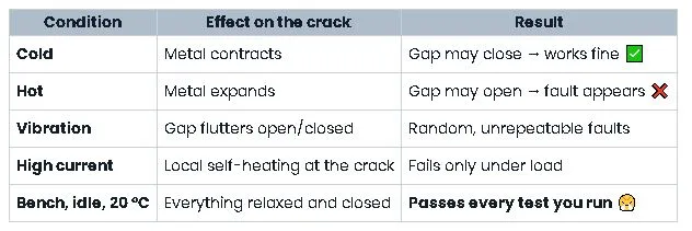
You said it perfectly: components don’t announce their failures.
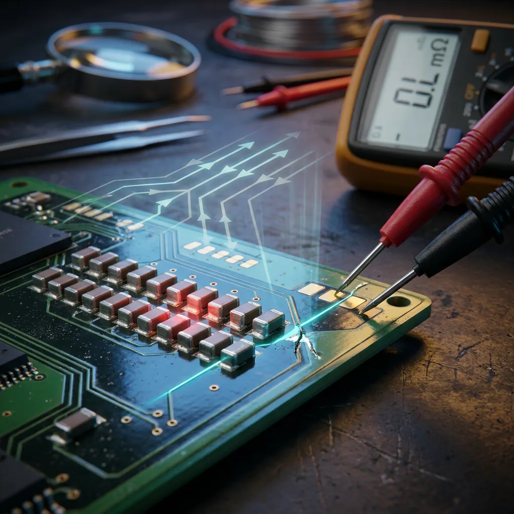
A shorted ceramic capacitor looks exactly like its healthy neighbors.
A cracked solder joint hides under a perfectly shiny looking blob.
That single fact drives everything in this course: in-circuit readings lie, and you must learn how they lie.
Why the Analog Meter Earns Its Place
Your instinct about the analog meter especially on the X10K range is sound, and here’s the reasoning:
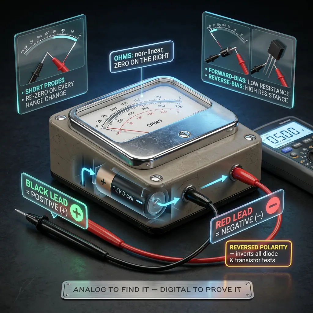
The key mental note: on most analog ohmmeters the internal battery polarity is reversed the black lead is positive.
Get this backwards and every diode and transistor test you do will be inverted.
Also remember: the ohm scale is non-linear and reversed (zero on the right), and you must short the probes and re-zero every time you change range.
Rule of thumb for the course: analog to find it, digital to prove it.
Identifying Components
Before testing, you must name the thing.
Train your eye on:
- Body shape and markings axial vs. radial, DIP vs. SOIC, TO-92/TO-220/TO-247 outlines
- Numbering systems 1N = diode, 2N/BC/BD/TIP = transistor, LM/TL/NE = IC, 78xx/79xx = regulators
- Colour bands and EIA codes 4/5-band resistors, 3-digit and 4-digit SMD codes (103 = 10 kΩ), the letter-code (4R7, 1M0)
- Board silkscreen R, C, L, D, Q (transistor), U (IC), T (transformer), F (fuse), VR/RV (variable), X/Y (crystal)
That silkscreen prefix is your first free clue about what a suspicious part is supposed to do.

How Components Actually Die
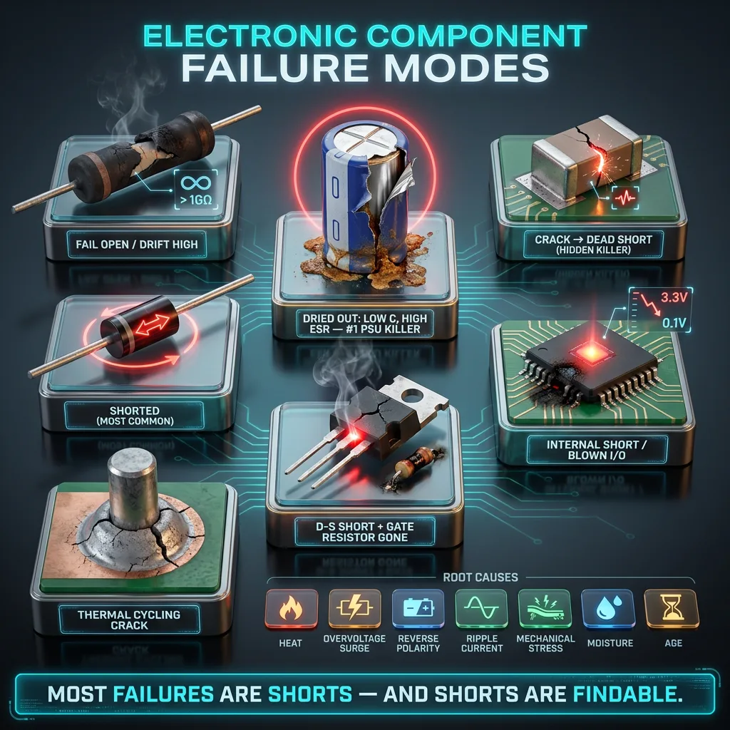
Understanding failure modes tells you what to look for:
- Resistors — usually fail open (or drift high); fusible/low-value types go open silently
- Electrolytic capacitors — dry out → capacitance drops, ESR rises; or short. The #1 cause of power-supply faults
- Ceramic caps — crack mechanically → dead short (a favourite hidden killer)
- Diodes — short (most common), then open
- Transistors/MOSFETs — collector-emitter or drain-source short, often taking the gate resistor with them
- ICs — internal short pulling a rail down, or a blown I/O pin
- Solder joints — thermal cycling → cracked ring around a heavy component’s pin
- Root causes — heat, overvoltage/surge, reverse polarity, ripple current, mechanical stress, moisture, and simple age
Notice how many of these are shorts. That’s good news: shorts are findable.
The Golden Rules of Testing
- Power off. Always. Then wait, then verify — bulk capacitors hold lethal charge long after the light goes out.
- Discharge big caps through a resistor, never a screwdriver.
- Look before you probe. Burnt, bulged, browned, cracked, leaking, smelling. Free answers.
- Compare, don’t judge. Identical parts on the same board are your best reference.
- In-circuit readings are always ≤ the true value — parallel paths pull resistance down.
- When in doubt, lift one leg. Isolating one pin turns a lying measurement into an honest one.

In-Circuit vs. Out-of-Circuit
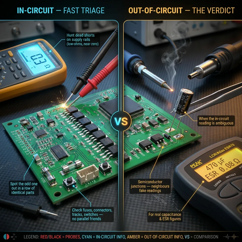
In-circuit is fast triage.
Use it to:
- Hunt for dead shorts across supply rails (low-ohms range, look for near-zero)
- Spot the odd one out among a row of identical parts
- Check fuses, connectors, tracks, and switches these have no sneaky parallel friends
Out-of-circuit is verdict.
Desolder (or lift one leg) when:
- The in-circuit reading is ambiguous
- Semiconductor junctions are involved (neighbouring parts fake the readings constantly)
- You need a real capacitance or ESR figure
Your Standard Test Set
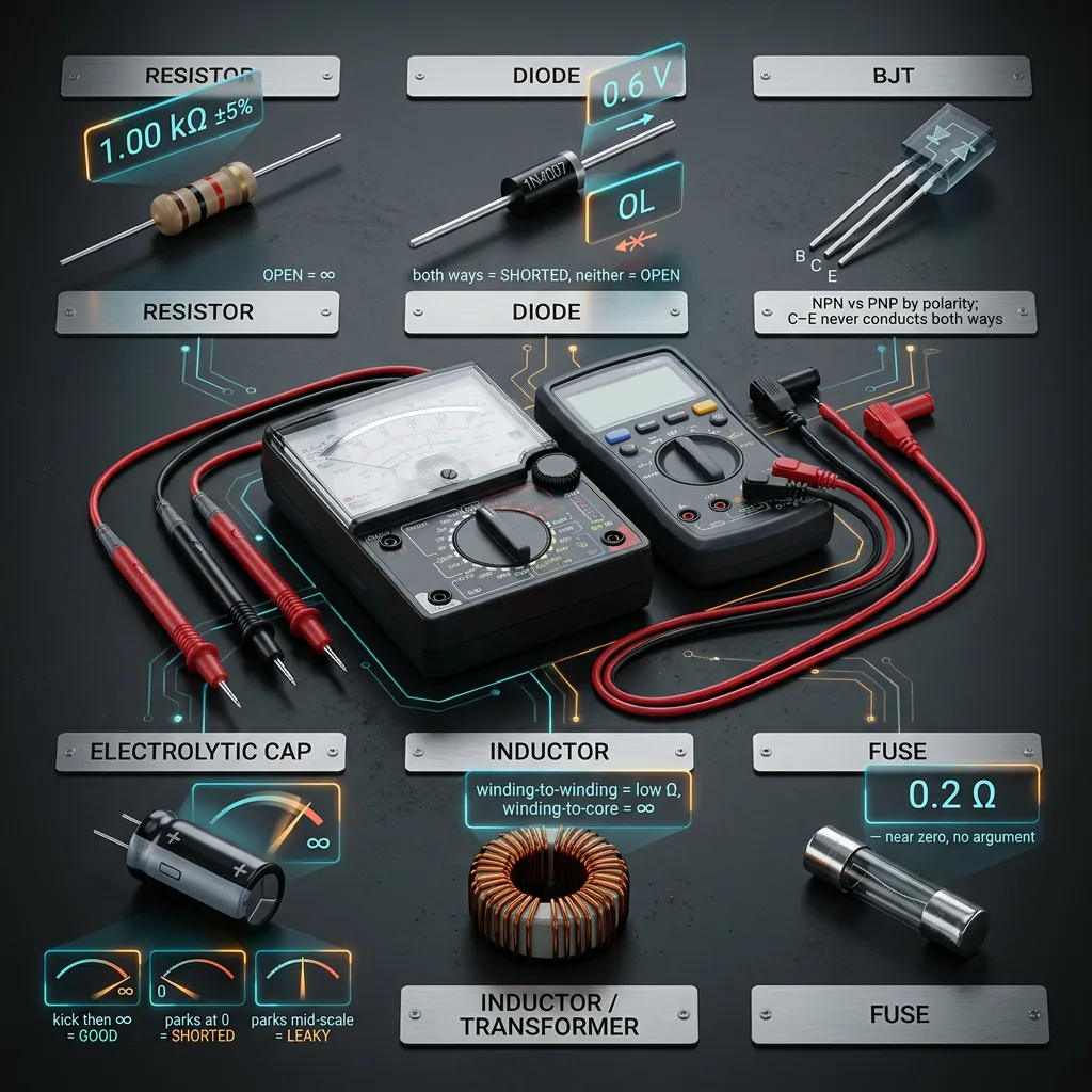
- Resistor — ohms range; compare to colour code, ±tolerance. Open = infinity.
- Diode — one direction conducts, the other doesn’t. Conducting both ways = shorted. Neither = open.
- BJT — treat as two diodes back-to-back from the base. Identify base first, then decide NPN vs. PNP by which polarity conducts. C–E must never conduct both ways.
- Electrolytic cap — analog needle should kick then drift back toward infinity. No kick = open. Needle parks near zero = shorted. Parks mid-scale = leaky (this is where analog shines).
- Inductor/transformer — low resistance winding-to-winding, infinite winding-to-core.
- Fuse — near zero ohms, no argument.
Your Practical Plan
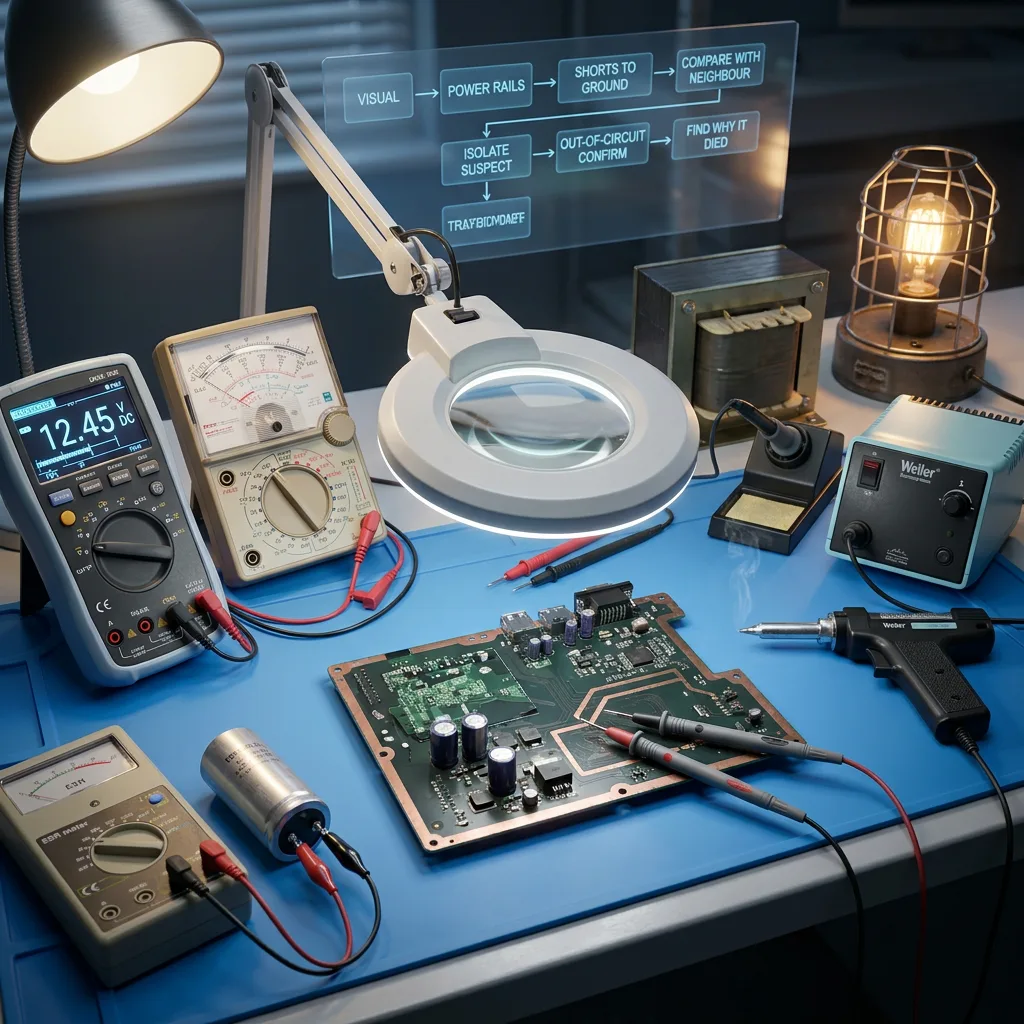
Bench kit: digital meter, analog meter, ESR meter, desoldering tools, isolation transformer or series-lamp limiter, magnifier, and good light.
Workflow every single time: Visual → power rails → shorts to ground → compare-with-neighbour → isolate suspect → out-of-circuit confirm → find why it died before fitting the replacement.
That last step matters most.
A component that failed usually had a reason, and a fresh part dropped into an unchanged fault condition simply becomes the next victim.
Next lesson, we can put the analog meter on the bench and walk through the X10K range technique in detail leakage hunting, junction behaviour, and reading the needle’s story rather than just its final position.